30+ Attic Fan Diagram Circuit Pics. Below is the circuit diagram for temperature controlled dc fan using thermistor as temperature sensor the key component of this temperature controlled fan circuit is thermistor, which has been used to detect the rise in temperature. I would be bypassing the thermostat and powering the fan directly, but wouldn't power feed back to the thermostat as well?
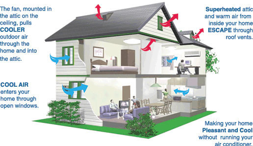
How does a whole house fan work? | Centric Air from www.centricair.com When the temperature reaches 35°c the controller circuit will start to work. Measure with a thermometer the air temperature close to the sensor. Fan regulator connection diagram and internal circuit explanation reviewed by.
Temperature controlled fan circuit operation.
The variable resistor placed in this circuit is vr1 500kω, connect variable resistor to increase resistance in clock wise rotation then only you can get high speed fan rotation when you rise the variable resistor. Use the main fuse box or circuit breaker box to shut it off. Turn off the electricity in your attic. An attic fan can be gable mounted or roof mounted.
Bagikan Artikel ini
Belum ada Komentar untuk "Attic Fan Diagram Circuit"

Belum ada Komentar untuk "Attic Fan Diagram Circuit"
Posting Komentar